Building an ESP32 Soil Moisture Monitor for Your Grow System
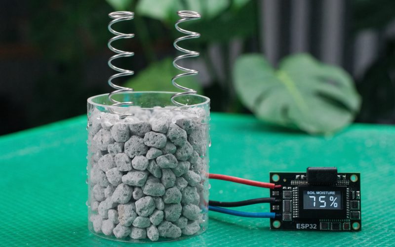
Overwatering and underwatering are the most common reasons beginner grows fail. Not light, not nutrients, not pH: water. Too much and roots suffocate. Too little and the plant stresses, stunts, and eventually dies. The maddening part is that both problems look the same at first: drooping, yellowing leaves.
A $3 capacitive soil moisture sensor and an ESP32 eliminate the guesswork. Instead of probing the growing medium with your finger or lifting a pot to estimate weight, you get a continuous percentage reading, and if you spend another 20 minutes on firmware, an alert on your phone when the reading drops below a threshold you set.
This guide walks through the complete build: sensor selection, wiring, calibration, firmware, WiFi reporting, and where to physically place the sensor in different hydroponic systems. If you already know you want to automate irrigation rather than just monitor, this is the foundation you build on; the monitoring layer comes before the relay control layer, every time.
Why Monitor Soil Moisture Automatically
Manual watering schedules are approximations. They are based on average plant water consumption under average conditions, but plants do not consume water on an average schedule. A hot, low-humidity day drives transpiration up by 30-50%. A cloudy stretch reduces it. New seedlings need far less water than established plants. Fruiting plants entering a heavy load phase pull water at rates that surprise even experienced growers.
The result of fixed schedules is systematic error. You water on Tuesday and Friday regardless of what the plant actually needs, and you discover the problem when you see symptoms, by which point you have already had several days of suboptimal root zone conditions.
Automated monitoring solves this at the data layer. A capacitive sensor inserted in the root zone reports moisture percentage continuously. You can see the drydown curve after a watering event, understand how fast your specific plant in your specific environment consumes water, and set alerts at the threshold where you need to act. The sensor costs less than a bag of vermiculite.
For hydroponic systems specifically, moisture monitoring serves a different but equally important function. In coco and peat-based media, the goal is a specific moisture range: not saturated, not dry, but within a band that supports aerobic root respiration and nutrient uptake. In systems like Kratky or other passive setups, a sensor placed near the root zone can warn you when the air gap is getting large enough to stress roots before visual symptoms appear.
Capacitive vs. Resistive Sensors
There are two types of affordable soil moisture sensors on the market. Understanding why one fails and the other does not matters if you want a sensor that is still working in three months.
Resistive sensors are the cheap fork-style probes that come in kits. They have two metal tines separated by a small gap. The sensor applies a small voltage across the tines and measures the resistance of the medium between them. More moisture means lower resistance; lower resistance means higher current. This works fine in the first hours of testing. The problem is the physics of what you have built: two dissimilar metals with a voltage across them, submerged in an electrolyte (wet growing medium is an electrolyte). This is the definition of a galvanic cell. Electrolytic corrosion begins immediately. Within days in continuously wet coco or soil, the probes are visibly corroded. Within weeks, the calibration has drifted enough to make readings meaningless. Some growers try running the sensor in a pulsed mode (only power it during readings) to slow corrosion, but this is fighting the fundamental design; the geometry requires current through the medium.
Capacitive sensors solve this by not passing current through the medium. Instead, the sensing element is a copper trace on a PCB that acts as one plate of a capacitor, with the growing medium acting as the dielectric between the trace and a ground plane. The dielectric constant of water (approximately 80) is much higher than that of air (approximately 1) or dry growing medium (approximately 3-4). As moisture increases, the dielectric constant of the medium around the sensor rises, which increases the capacitance, which the sensor’s oscillator circuit converts to a voltage. The probe never completes a circuit through the medium. No corrosion.
Practical options in the $2-6 range:
- DFROBOT SEN0193: well-documented, 3.3V and 5V compatible, reliable calibration curve, good for production builds
- Generic “capacitive v1.2” module: widely available from Asian suppliers on Amazon and AliExpress, usually fine, but calibration values can vary significantly between units from the same listing
- Adafruit STEMMA QT Soil Sensor: uses I2C (not analog), higher cost (~$8), but gives temperature in addition to moisture and works well if you are already using I2C on the bus
For this guide, I am using the generic v1.2 or SEN0193; the analog output wiring is identical for both, and calibrating your specific unit takes five minutes.
Parts List
| Component | Spec / Recommended Option | Approx. Cost |
|---|---|---|
| ESP32 dev board | 30-pin, any brand (Espressif DevKit, DOIT ESP32 DEVKIT V1, etc.) | $4-8 |
| Capacitive soil moisture sensor | DFROBOT SEN0193 or generic capacitive v1.2 | $2-5 |
| Jumper wires | Female-to-female, 20cm | $2 |
| USB cable | Micro-USB or USB-C (match your specific ESP32 board) | $2 |
| Breadboard | 400-tie (optional, useful for prototyping before permanent installation) | $3 |
Total: approximately $13-20, assuming you already have a USB power supply. If you are adding a relay for pump control later, budget an extra $3-6 for a 5V single-channel relay module.
One note on the ESP32 board selection: the 30-pin DOIT DevKit V1 layout is the most commonly documented and has the widest community support. The 38-pin variants have more GPIO but the pinout varies between manufacturers and some datasheets are incorrect. If you are new to ESP32, start with a 30-pin board from a listed vendor (DOIT, AZ-Delivery, HiLetgo) where the pinout is well-established.
Wiring the Sensor to the ESP32
The capacitive sensor has three connections. The wiring is the same regardless of whether you are using the SEN0193, the generic v1.2, or most other analog capacitive sensors.
Pin mapping:
| Sensor Pin | ESP32 Pin | Notes |
|---|---|---|
| VCC | 3.3V | Use 3.3V, not 5V. Most capacitive sensors are 3.3V-native. Some tolerate 5V but the analog output range may not map cleanly to the ESP32’s 0-3.3V ADC input. |
| GND | GND | Any GND pin on the ESP32. |
| AOUT (analog output) | GPIO 34 | ADC1 channel 6. Any ADC1 pin works (GPIO 32-39); avoid ADC2 if you plan to use WiFi. |
That is the complete wiring. Three wires, five minutes with female-to-female jumpers if you are prototyping on a breadboard.
A few things worth understanding about the ESP32’s ADC that affect sensor accuracy:
The ESP32’s ADC is 12-bit, which means it produces values from 0 to 4095 corresponding to 0V to 3.3V. However, the ESP32’s ADC is not particularly linear; it has known nonlinearity at the low and high ends of its range (below about 150 and above about 3800). This matters less than you might expect for a moisture sensor, because the sensor’s output typically occupies the middle range (roughly 800-3500 ADC), well inside the linear region.
The ADC also does not have the input protection you would find on a dedicated measurement IC. Do not connect anything to the ADC pins that could exceed 3.3V. The sensor’s AOUT pin will be within this range if you powered the sensor from the ESP32’s 3.3V rail.
If you are using a 5V USB power source and powering the ESP32’s 3.3V pin from it (rather than the VIN pin), double-check that the voltage regulator on your ESP32 board is handling that correctly. Underpowered boards produce noisy ADC readings, a symptom that looks like a faulty sensor but is actually a power supply issue.
Reading the Sensor: Raw ADC Values
Before worrying about calibration or percentage conversion, it is worth understanding what the sensor actually outputs.
The capacitive sensor outputs a voltage between 0V and VCC in inverse proportion to moisture content. More moisture means lower voltage output, which means a lower ADC reading. This is counterintuitive at first; you might expect higher moisture to produce a higher reading. The inversion is a consequence of how the sensor’s RC oscillator circuit works: higher capacitance (more moisture) shifts the oscillation frequency in a direction that produces lower output voltage.
Practically, this means:
- Dry medium (air): sensor output close to VCC, ADC reading approximately 3000-4095
- Fully saturated medium (submerged): sensor output close to 0V, ADC reading approximately 800-1500
The exact range depends on your specific sensor unit. Generic v1.2 modules can vary by 200-400 ADC units between units from the same order. This is why calibration is not optional; it is how you account for per-unit variation.
Connect the sensor to your ESP32, open the Arduino IDE Serial Monitor, and run this minimal sketch to see your raw values:
void setup() {
  Serial.begin(115200);
  pinMode(34, INPUT);
}

void loop() {
  int raw = analogRead(34);
  Serial.println(raw);
  delay(1000);
}
Hold the sensor in air: note the reading. Submerge just the probe section in a glass of water: note the reading. These two numbers are your calibration anchors. Write them down; you will use them in the next step.
Calibration Procedure
Calibration maps your sensor’s raw ADC range to a meaningful 0-100% moisture percentage. Without calibration, you have a number that tells you nothing about the actual state of your growing medium.
The procedure requires two reference measurements:
Step 1: Dry reference. Fill your growing container with your actual growing medium (coco coir, perlite mix, soil, rockwool, whatever you use). Let it dry completely, at least 24-48 hours in open air, or use freshly opened dry media straight from the bag. Insert the sensor probe into the medium to the same depth you plan to use during actual monitoring. Record the ADC reading. This is your DRY_VALUE. Expect something in the 3000-4095 range.
Step 2: Wet reference. Water the same medium to full saturation; water until runoff, wait 3-5 minutes for the water to distribute evenly, then insert the sensor again to the same depth. Record the ADC reading. This is your WET_VALUE. Expect something in the 800-1500 range.
The conversion formula uses Arduino’s built-in map() function:
moisturePercent = map(rawValue, DRY_VALUE, WET_VALUE, 0, 100)map() performs linear interpolation between two ranges. Since DRY_VALUE is numerically larger than WET_VALUE (the ADC reads high when dry), and we want 0% when dry and 100% when wet, we pass them in the order DRY_VALUE, WET_VALUE to invert the mapping. The function handles the inversion automatically.
After map(), apply constrain() to clamp values to the 0-100 range. Without it, readings outside your calibrated range produce negative numbers or values above 100, possible if the medium dries more than your reference, or if you accidentally submerge the board body (not just the probe).
One calibration subtlety: calibrate in the same medium you will use for monitoring. A sensor calibrated in coco coir will read incorrectly in perlite. The dielectric properties of the medium itself are part of the measurement; different materials have different baseline dielectric constants even when dry. If you switch growing media, re-calibrate.
Basic Firmware
This is the complete working firmware for a standalone moisture monitor. It reads the sensor every 5 seconds and prints the raw ADC value and calculated moisture percentage to Serial.
#include <Arduino.h>

const int MOISTURE_PIN = 34;
const int DRY_VALUE = 3500;   // replace with your calibrated dry reading
const int WET_VALUE = 1200;   // replace with your calibrated wet reading
const int READ_INTERVAL = 5000; // milliseconds between readings

void setup() {
  Serial.begin(115200);
  pinMode(MOISTURE_PIN, INPUT);
  Serial.println("Soil Moisture Monitor — starting up");
}

void loop() {
  int rawValue = analogRead(MOISTURE_PIN);
  int moisturePercent = map(rawValue, DRY_VALUE, WET_VALUE, 0, 100);
  moisturePercent = constrain(moisturePercent, 0, 100);

  Serial.printf("Raw: %d | Moisture: %d%%\n", rawValue, moisturePercent);
  delay(READ_INTERVAL);
}
A few implementation notes on why this code is structured this way:
pinMode(MOISTURE_PIN, INPUT) is technically not required for ADC-capable GPIO pins on the ESP32 (they default to input mode), but it is good practice to make pin intent explicit. If you are reading this sketch 6 months later, the intent is unambiguous.
Serial.printf() is more readable than string concatenation for formatted output. If you are using an older Arduino core that does not support printf on Serial, substitute:
Serial.print("Raw: ");
Serial.print(rawValue);
Serial.print(" | Moisture: ");
Serial.print(moisturePercent);
Serial.println("%");
The 5-second read interval (READ_INTERVAL = 5000) is fine for bench testing. For deployed monitoring, you can extend this significantly; moisture does not change meaningfully second-to-second in a grow medium. A 30-second or 60-second interval reduces ESP32 power consumption if you are running on a battery, and produces cleaner data logs without redundant readings.
If you see noise in the raw readings (values jumping ±50-100 ADC units between reads), take an average over multiple samples instead of a single read:
int readMoistureSensor(int pin, int samples = 10) {
  long total = 0;
  for (int i = 0; i < samples; i++) {
    total += analogRead(pin);
    delay(10);
  }
  return total / samples;
}
Replace analogRead(MOISTURE_PIN) with readMoistureSensor(MOISTURE_PIN) in the loop. Ten samples with 10ms spacing takes 100ms and smooths out most ADC noise.
Adding WiFi and Sending Data to a Dashboard
The basic firmware is useful for bench testing and wired monitoring. For a deployed grow room sensor, you want data you can view without pulling up a laptop. Two practical options: send readings to an HTTP endpoint (a web server, a home automation platform’s API, or a service like Datacake), or publish to an MQTT broker.
MQTT is the better choice for grow room sensor networks. It is designed for low-overhead, many-to-many messaging between IoT devices; you can have a single broker receive readings from a dozen sensors and fan them out to Home Assistant, a custom dashboard, and an alert system simultaneously, without any of those consumers needing to know about each other.
Here is the complete WiFi + MQTT firmware:
#include <Arduino.h>
#include <WiFi.h>
#include <PubSubClient.h>

// WiFi credentials
const char* WIFI_SSID = "your-ssid";
const char* WIFI_PASSWORD = "your-password";

// MQTT broker — IP address of your broker (e.g., Mosquitto on a Raspberry Pi)
const char* MQTT_BROKER = "192.168.1.100";
const int MQTT_PORT = 1883;
const char* MQTT_CLIENT_ID = "growroom-sensor-1";
const char* MQTT_TOPIC = "growroom/sensor1/moisture";

// Sensor config
const int MOISTURE_PIN = 34;
const int DRY_VALUE = 3500;
const int WET_VALUE = 1200;
const int READ_INTERVAL = 30000; // 30 seconds

WiFiClient wifiClient;
PubSubClient mqttClient(wifiClient);

void connectWiFi() {
  Serial.print("Connecting to WiFi");
  WiFi.begin(WIFI_SSID, WIFI_PASSWORD);
  while (WiFi.status() != WL_CONNECTED) {
    delay(500);
    Serial.print(".");
  }
  Serial.println();
  Serial.printf("Connected. IP: %s\n", WiFi.localIP().toString().c_str());
}

void connectMQTT() {
  while (!mqttClient.connected()) {
    Serial.print("Connecting to MQTT broker...");
    if (mqttClient.connect(MQTT_CLIENT_ID)) {
      Serial.println("connected.");
    } else {
      Serial.printf("failed (state=%d), retrying in 5s\n", mqttClient.state());
      delay(5000);
    }
  }
}

int readMoistureSensor(int pin, int samples = 10) {
  long total = 0;
  for (int i = 0; i < samples; i++) {
    total += analogRead(pin);
    delay(10);
  }
  return total / samples;
}

void setup() {
  Serial.begin(115200);
  pinMode(MOISTURE_PIN, INPUT);
  mqttClient.setServer(MQTT_BROKER, MQTT_PORT);
  connectWiFi();
  connectMQTT();
}

void loop() {
  if (!mqttClient.connected()) {
    connectMQTT();
  }
  mqttClient.loop();

  int rawValue = readMoistureSensor(MOISTURE_PIN);
  int moisturePercent = map(rawValue, DRY_VALUE, WET_VALUE, 0, 100);
  moisturePercent = constrain(moisturePercent, 0, 100);

  char payload[16];
  snprintf(payload, sizeof(payload), "%d", moisturePercent);
  mqttClient.publish(MQTT_TOPIC, payload);

  Serial.printf("Published moisture: %d%% (raw: %d)\n", moisturePercent, rawValue);
  delay(READ_INTERVAL);
}
The PubSubClient library needs to be installed via the Arduino Library Manager (search “PubSubClient” by Nick O’Leary). This is the standard MQTT library for Arduino and ESP32; it is well-maintained and handles reconnection correctly.
The connectMQTT() function uses a blocking reconnect loop, which is acceptable for a sensor that is not doing anything else while waiting. If you are building a system that also controls output (pumps, relays), use a non-blocking reconnect pattern instead to prevent the loop from stalling.
If you do not want to run a local MQTT broker, CloudMQTT (free tier) and HiveMQ Cloud (free tier, 10 connections) are hosted options that work with PubSubClient with no code changes beyond updating the broker address, port (usually 8883 for TLS), and adding TLS client setup.
Threshold-Based Alerts
Reading is useful. Acting on readings is what prevents crop loss.
The simplest alert logic uses a threshold check in the sensor loop. When moisture drops below a defined percentage, publish to a dedicated alert topic:
const int ALERT_THRESHOLD = 30; // alert when below 30% moisture
const char* MQTT_ALERT_TOPIC = "growroom/sensor1/alerts";

// Inside loop(), after calculating moisturePercent:
if (moisturePercent < ALERT_THRESHOLD) {
  char alertMsg[64];
  snprintf(alertMsg, sizeof(alertMsg), "LOW MOISTURE: %d%% on sensor 1", moisturePercent);
  mqttClient.publish(MQTT_ALERT_TOPIC, alertMsg);
  Serial.println(alertMsg);
}
This publishes an alert message every READ_INTERVAL seconds as long as the condition is true. For most alert systems (Home Assistant, Node-RED), publishing the same alert repeatedly is fine; the receiving system can deduplicate. If you want to send the alert only once when the threshold is first crossed (and again only after it recovers), use a state variable:
bool alertActive = false;

// Inside loop():
if (moisturePercent < ALERT_THRESHOLD && !alertActive) {
  mqttClient.publish(MQTT_ALERT_TOPIC, "LOW MOISTURE — check grow room");
  alertActive = true;
} else if (moisturePercent >= ALERT_THRESHOLD && alertActive) {
  mqttClient.publish(MQTT_ALERT_TOPIC, "MOISTURE RECOVERED");
  alertActive = false;
}
This version sends one alert when moisture drops below the threshold and one recovery message when it rises back above. In Home Assistant, an MQTT automation can route these messages to a mobile notification via the companion app, or to any webhook-based notification service (Pushover, Ntfy, Telegram bot).
Choose your threshold based on your growing medium, not an arbitrary number. Coco coir and perlite mixes are typically watered at 30-40% and considered “dry” below 20-25%. Potting soil holds more water at the same percentage reading (because the medium itself has different dielectric properties). After your first full grow with the sensor, you will have enough data to set a meaningful threshold based on observed plant response.
Installing in a Hydroponic System
Placement matters as much as the sensor itself. The same moisture percentage reading means different things depending on where the probe is positioned.
Kratky systems. In monitoring a Kratky reservoir, the useful measurement is not moisture content of a medium; it is reservoir level. A moisture sensor inserted vertically near the base of the net pot measures whether the bottom of the root zone is in contact with the solution. As the reservoir drops, the sensor reads lower moisture, warning you before the air gap becomes large enough to stress roots. Mount the probe at the intended minimum reservoir depth. When it reads below 20-30%, add nutrient solution.
DWC systems. For DWC water level and temperature monitoring, a single capacitive sensor at the reservoir waterline can track whether the solution is near the net pot. More useful in DWC is combining the moisture sensor with a DS18B20 waterproof temperature probe in the reservoir; together you get a picture of root zone conditions without a dedicated water level float sensor.
Coco/drip systems. These are the primary use case for moisture sensing. Insert the probe into the root zone at mid-depth in the container, not at the top (where surface evaporation dominates) and not at the bottom (where runoff pools). The probe should be in the zone where the majority of active root tips are located, which is typically the middle third of the container. In a 3-gallon coco container, the target depth is 4-6 inches from the surface.
Sensor orientation. Keep the PCB (circuit board body) above the medium surface and the sensing probe pointing down into the medium. Most boards are not conformal-coated and are not waterproof. The probe trace itself handles moisture exposure by design. The capacitor, oscillator IC, and voltage regulator on the board body do not.
Waterproofing the board. If your sensor will be in a high-humidity environment (most grow tents qualify), apply liquid electrical tape or clear conformal coating to the board body, avoiding the probe trace area below the board’s fill line. This protects against condensation on the components. Do not coat the sensing area; that would alter the calibration and reduce sensitivity.
For permanent installations, mount the ESP32 outside the grow tent or in a ventilated enclosure. Route the sensor cable in through a cable gland. A standard 3-wire 22 AWG cable works for sensor cable runs up to 3-4 meters without significant voltage drop on the ADC signal line. For longer runs, consider using a sensor with a digital output protocol (I2C, UART) or a 4-20mA current loop interface to maintain signal integrity.
Adding Temperature and Humidity
A moisture reading in isolation gives you one dimension of root zone information. Pairing it with temperature and humidity from a DHT22 or SHT31 sensor completes the picture for understanding plant water demand.
High temperature and low humidity mean high vapor pressure deficit (VPD), which drives high transpiration, which means plants pulling water from the medium faster than your scheduled watering provides. When your moisture sensor reads a rapid drydown, faster than historical average, it often corresponds to a VPD spike. If you can add a DHT22 for temperature/humidity alongside your moisture sensor and log both, you can correlate drydown rate with VPD and start to predict when irrigation events are needed rather than reacting to low-moisture alerts.
The DHT22 connects to any GPIO pin that supports digital input and uses a single-wire protocol. Add it to the same sketch with the DHT library:
#include <DHT.h>

const int DHT_PIN = 27;
const int DHT_TYPE = DHT22;
DHT dht(DHT_PIN, DHT_TYPE);

// In setup():
dht.begin();

// In loop(), after reading moisture:
float temperature = dht.readTemperature();
float humidity = dht.readHumidity();

char envPayload[64];
snprintf(envPayload, sizeof(envPayload), "{\"temp\":%.1f,\"rh\":%.1f}", temperature, humidity);
mqttClient.publish("growroom/sensor1/environment", envPayload);
This publishes a JSON payload with temperature and relative humidity to a separate MQTT topic. In Home Assistant, configure this as a MQTT sensor with value_template: "{{ value_json.temp }}" to extract individual values from the JSON.
What to Build Next
This sensor is the first layer of an automated grow system. The natural progression:
Automated watering. Add a 5V single-channel relay module between the ESP32 and a submersible pump. When moisturePercent < WATER_THRESHOLD, close the relay for a set duration (start with 5-10 seconds for a small drip emitter), then check moisture again after 2 minutes to see if the target was reached. This is open-loop control; you are watering for a fixed duration, not until a target moisture is reached. A proportional controller (water longer when moisture is lower) is the next refinement.
Water temperature. Add a DS18B20 waterproof temperature probe to the reservoir. Combined with the moisture sensor, you have the two most important root zone parameters for DWC water level and temperature monitoring in a single ESP32 build.
Home Assistant dashboard. If you have a Home Assistant instance, the MQTT integration takes 5 minutes to configure. From there you get persistent data logging, historical charts, notification automations, and the ability to see all sensor data in one dashboard regardless of how many sensors you have deployed.
Multiple sensors. The MQTT topic structure in this firmware (growroom/sensor1/moisture) is intentionally designed to scale. Add a second ESP32 with a second sensor and publish to growroom/sensor2/moisture. No changes needed to the broker or Home Assistant; the new topic auto-populates.
For more ESP32 projects in the grow room context and a full index of automation guides, the smart irrigation and IoT guide index covers sensors, actuators, controller builds, and Home Assistant integrations across all system types.
If you are earlier in the process and have not yet committed to a hydroponic system type, read choosing your hydroponic system before designing your monitoring setup; sensor placement strategy differs significantly between DWC, Kratky, NFT, and media-based systems.
The complete build (sensor, ESP32, wiring, calibration, and basic firmware) takes about two hours from unboxing to a working Serial output showing live moisture percentages. Adding WiFi and MQTT takes another hour. By the end of that afternoon, you have a system that tells you exactly what is happening in your root zone, continuously, and will tell your phone when something needs attention.
The skill compounds. Once you can read a sensor and publish to MQTT, every other IoT integration in the grow room follows the same pattern. Temperature, humidity, CO2, reservoir level, pump state: same ESP32, same broker, different sensor on a different pin. Build the moisture monitor first, understand the workflow, then expand from there.
[ FAQ ]
Why should I use a capacitive moisture sensor instead of resistive?
Resistive sensors pass a small electrical current through two metal probes in the growing medium and measure conductance as a proxy for moisture. The problem is that current flow through wet soil causes electrolytic corrosion on the probes; within days to weeks of continuous operation, the probes oxidize, resistance readings drift, and eventually the sensor becomes unusable. Capacitive sensors have no metal probes in contact with the medium. Instead, they measure how the dielectric constant of the material around the electrode pad changes with moisture content. Dry medium has a low dielectric constant; water has a high one. No current flows through the medium, no corrosion occurs, and the sensor operates accurately for years. The cost difference is negligible: $2-5 for a good capacitive sensor versus $1-2 for a fork-style resistive sensor. The performance difference is not negligible.
Which GPIO pins can I use for analog input on the ESP32?
The ESP32 has two ADC units. ADC1 (GPIO 32-39) is the one you want for analog reads in most firmware. ADC2 (GPIO 0, 2, 4, 12-15, 25-27) shares silicon with the WiFi radio, which means ADC2 readings are unreliable or unavailable when WiFi is active. For a moisture monitor that sends data over WiFi, always use ADC1 pins. Within ADC1, GPIO 34-39 are input-only (no internal pull-up or pull-down), which is fine for a sensor's analog output. Good choices: GPIO 34, 35, 36, 39. Avoid GPIO 36 and 39 if you are using them for other purposes, as they are also the internal hall sensor and touch sensor inputs on some packages.
How do I calibrate my moisture sensor?
Calibration establishes the ADC readings that correspond to 0% and 100% moisture in your specific growing medium. Step one: fill a container with your dry growing medium (coco coir, perlite, potting mix, or whatever you use), insert the sensor probe, and record the ADC value. This is your DRY_VALUE, typically 3000-4095 on an ESP32. Step two: saturate the same medium with water until runoff, wait 2-3 minutes for the water to distribute, reinsert the sensor, and record the ADC value. This is your WET_VALUE, typically 800-1500. Update those constants in the firmware and redeploy. Re-calibrate any time you change growing medium types.
Can I run this firmware without WiFi?
Yes. The basic firmware sketch in this guide does not use WiFi at all; it reads the sensor and prints to Serial. You can use that exact sketch for bench testing, data logging via a USB connection to your laptop, or in environments where WiFi is not available. If you want data logging without a laptop connection, add an SD card module (most SPI-capable pins on the ESP32 work) and write readings to a CSV file. The WiFi and MQTT sections are additive layers on top of the working base firmware, not prerequisites.
How do I connect the ESP32 moisture data to Home Assistant?
The cleanest integration is MQTT. Run Mosquitto (an open-source MQTT broker) on the same machine that runs Home Assistant, or use the Mosquitto add-on if you are running Home Assistant OS. In Home Assistant, add an MQTT sensor entity that subscribes to the topic your ESP32 publishes to, for example, 'growroom/sensor1/moisture'. The MQTT Discovery protocol can automate this: if you publish a discovery payload to 'homeassistant/sensor/growroom_moisture/config' with the correct JSON schema, Home Assistant will create the entity automatically without any manual YAML configuration. Once the entity exists, you can build automations, dashboard cards, and threshold alerts entirely within Home Assistant's interface.